AD 60 Class Beyer-Garratt
1.5" scale 7.5" Gauge
Updated to May 2007
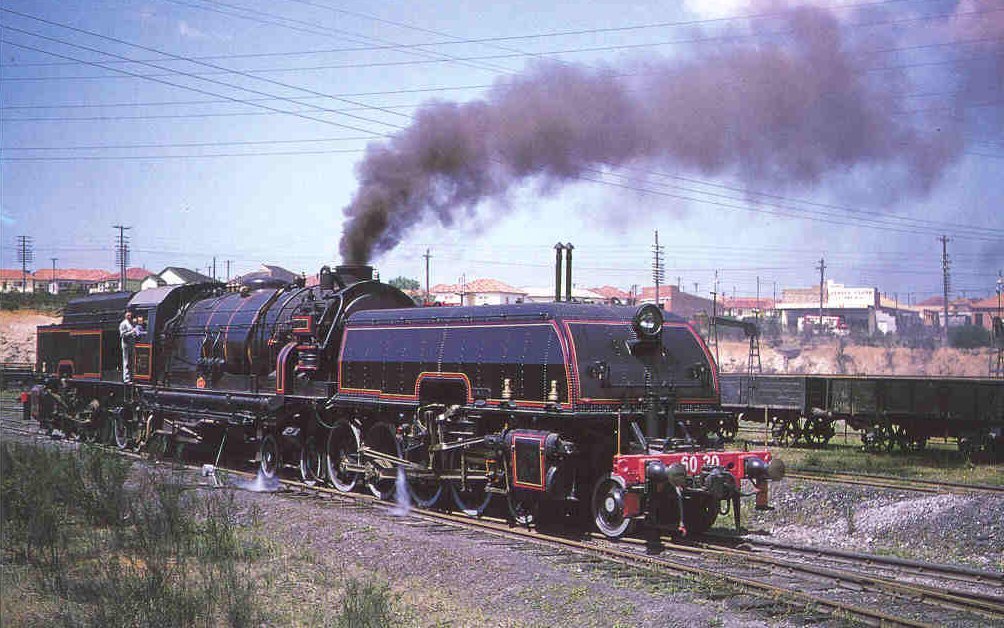
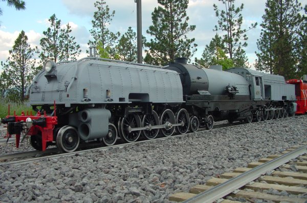
The goal is to replicate this image in 1.5" scale
(except the smoke :) 6020 in 1955
I think Ive always been interested in things that
are a little different and in the world of steam locomotives
Beyer-Garratts would always fit into that category.
In late 1999, Id been corresponding on things steam via the Internet
with a mining engineer named Russell Dunn from Perth, Western Australia.
Russell asked for help locating a man in our part of the world for
assistance in building a Willamette geared locomotive. I was able to get
these two guys hooked up and the Russell in return, graciously bought me a
years subscription to the Australian Model Engineer magazine (AME).
Id been thinking about a new larger loco than the early American 2-6-0
that Id been running and was looking around for ideas. Several ideas
were on the table when the latest copy of the AME arrived. If you have
never seen this magazine, it really is of excellent quality. Anyway,
browsing through it I spotted a for sale ad for a partially completed New
South Wales Railway (NSWR) AD-60 class 4-8-4 + 4-8-4 Beyer-Garratt in
1.5 scale.
I sent Russell an e-mail asking if he knew anything about it. He said no
but stated that he was currently working at a mine just 100 miles from the
sellers address and would be happy to go and take a look on his day off
the following weekend.
After his inspection Russell sent me a detailed e-mail with images listing
all the parts and his assessment of the workmanship.
I called the seller
and we made a deal.
About 8 weeks later three very large crates were delivered to me.
What I received was a set of castings including the two engine unit mainframes which
themselves are one piece castings as per the prototypes. A full set of
finished sheet metal comprising of the front and rear tanks, boiler
cradle, cab and smoke box together with most of the parts to build a
copper boiler. The sheet metal work is of the highest quality. The
castings were just OK.
The story of the origin of this loco only then started to unfold and even
today I do not have the full story. What I do know is this: In the early
1970s the apprentices of the NSWR main works at Eastleigh near Sydney,
built a sectioned 1.5 scale model, I believe for the railway
headquarters, which was as prototypical as one could imagine even down to
the correct number of boiler tubes. That loco exists today and is on
display in the Power House Museum in Sydney, Australia. The patterns Im
told were supposed to have been scrapped after the one set of castings
were produced. Fortunately, they were not scrapped but instead were
spirited away by persons unknown and one more set of castings
produced. I do not know who cast the parts or where the patterns are
today.
Drawings came from three sources: two in Australia and interestingly also
from a guy in Georgia, USA. Most of the machined component drawings have
since been transferred into CAD to allow the code to be used for
machining.
One of the first decisions was to not use the copper boiler components.
Boiler regulations in this part of the world for copper are the same as
for Australia: 100 psi operating pressure and assembled by someone with a
welding ticket. The hobbyist here however, can still assemble a steel
boiler with up to a 150-psi max operating pressure. With the length of the
steam pipes involved, we decided to go with steel. This would allow if
needed the higher operating pressure regulations allow. We opted though for rolled-in
copper tubes.
The length of the tracks in the western US and Canada dictated the second
decision. The use of steel tires on all wheels. Annual mileages run by
miniature locomotives in this part of the world seem to increase every
year. All the clubs from British Columbia, Canada to California seem to be
extending their tracks and or, switching to steel rail (and plastic ties).
The third decision naturally followed the second, roller bearings on all
axels and sintered bronze bushings on every single moving joint beyond
there.
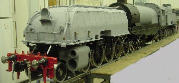
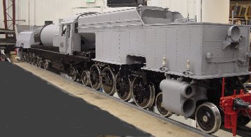
With those decisions made, construction started and progressed to the
point in 2003 that we had a rolling chassis to take to the 2003 Triennial
meet at Train Mountain in Oregon, USA. We used the opportunity not only to
show the work done so far to our peers in the hobby but also to do a
couple of test pushes early one morning through the labyrinth of
switches around the Train Mountain central station. The loco tracked
really well with no issues.
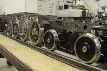
Highlights of the construction to that point were assembling the 700+
components in the fully equalized suspension system and using water-jet
technology (invented here in the Kent Valley of Western Washington) to
produce all the firebox components and the leaf springs.
The main springs are novel in that they are one piece. They work
as part of the equalization system but not as "springs" which we decided
were not necessary.
The project also benefited immensely from the acquisition of a 20 year
old, three-axis CNC Hurco mill that came to us in a very sorry state but
after a good going through has proven invaluable and very reliable.
Since June of 2003 the date of the image shown, work has concentrated on
the braking system, motion and valve gear. As I type this article in early
April 2005, the braking system is complete and most of the components for
the motion and valve gear are machined. All the motion parts were
water-jet cut from steel plate then machined on the Hurco.
The following significant challenge remains.
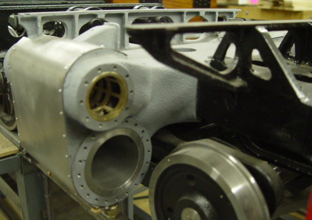
This involves casting the piston and valve guides, the steam turret, the
firebox door and the very unique and oblique top feed check (clack) valves
using the lost wax process from thermo jet printed patterns.
Work on these parts started in earnest recently after I paid a visit to
see and photograph the prototype 6039 at the Dorrigo Museum in New South
Wales, Australia and the sister 1.5 scale loco previously mentioned. To
date though we are still struggling!
Ive promised your editor an update to this article after the first
steaming.
No project of this type can be accomplished alone,
certainly not by me anyway! I owe a huge gratitude for inspiration, much
help, advice and passing of knowledge to many and in particular to the
following without whom this project would never have seen the light of
day:
Dennis Weaver, Geoff Robinson and Mike McDonald here
in the USA. Russell Dunn, Bob Farquah, Lyle James, Keith Jones, Colin
Hussey and the curator and staff of the Power House Museum in Australia,
Phil Heath, Jim Nolan, Bruce Walley and Brett Rogers in England.
Four prototypes still exist. 6029, 6039, 6040 and 6042
all in New South Wales. All have been out of service since 1973 although
6029 and 6039 ran in preservation until 1981.
The
article above first appeared in the June 2005 edition of "7 1/4 News"

Builders plate in 1.5" scale for
loco 6039
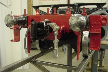
Pilot (Buffer) beam with dual Buckeye/Link couplings
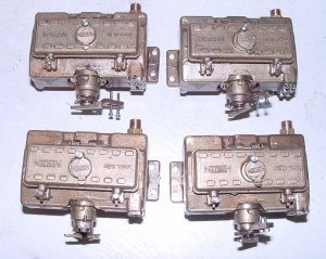
The four Nathan DV7 lubricators machined and ready to
install
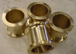
The four Steam brake cylinders under construction

Silver Brazing the 45 small tubes and 4 super heater
tubes in to the firebox tube plate . Note the three thermic siphons.
Boiler will be propane fired.
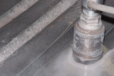
Water jet cutting of the Garratt rod blanks

Full set of Garratt Rod blanks after water jet cutting
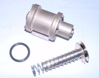
Finish Machined Brake Cylinder
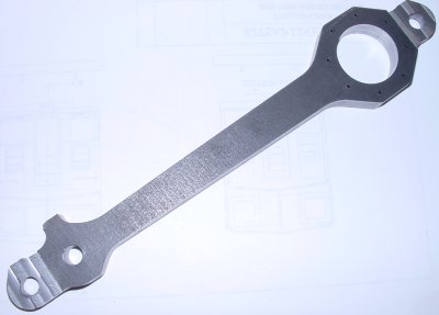
Partially machined rod

Spring rigging components note the "leaf springs" at the top....
Over 700 components in the spring rigging.
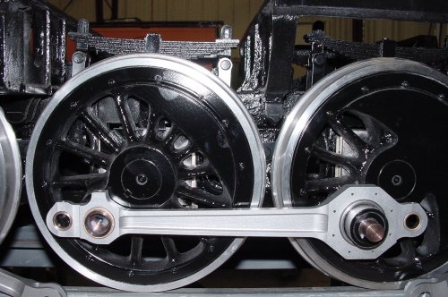
Rods and spring rigging
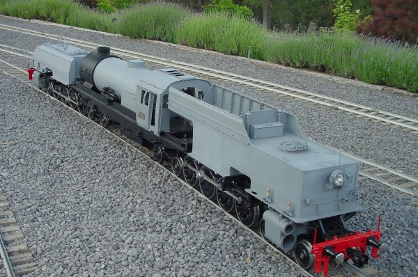
First track test, TM top loop
Pushed by a diesel to test tracking etc.
On to brake rigging,

Links and shoes are cast

Brake rigging shown here is laser cut from flat stock

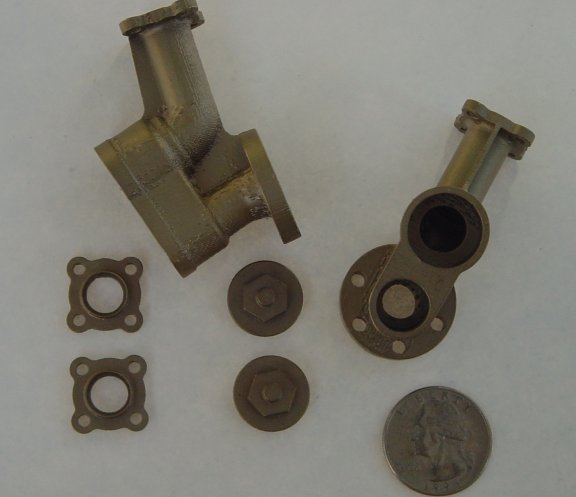
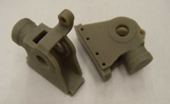
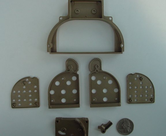
Finally, in June 2006, with the help of many, the waxes
have been produced for the 21 castings required to finish the project.
Below are the wax molds and the castings produced from
them
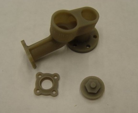

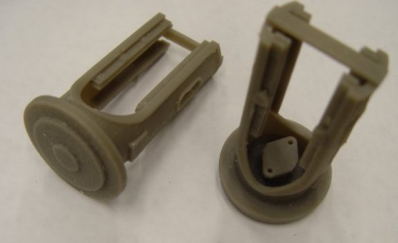
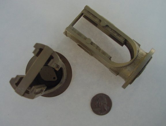

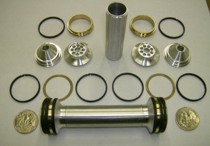
All of the components for one valve spool with another
shown assembled at the bottom of the image.

|